Posts

8051 Addressing Modes | Addressing modes of 8051 Microcontroller

Image
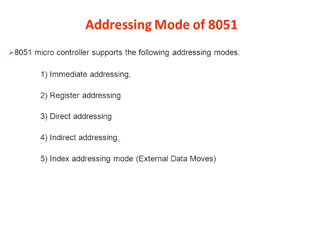
Addressing Modes :- The CPU can access data in a register or in memory or be provided as an immediate value. These various ways of accessing data are called addressing modes.       The 8051 provides a total of five distinct addressing modes.       They are as follows:-       1) Immediate addressing modes.       2) Register addressing modes.       3) Direct addressing modes.       4) Register indirect - addressing mode.       5) Indexed addressing mode. Let us study different modes with selective examples:- 1) Immediate Addressing mode:-                                     In This addressing mode, the source operated is a constant i.e. immediate data. Note that the immediate data must be preceded by the pound sign"#".        Example:-                 MOV A, # 82H                         ; load 82H into A                 MOV R4, # 100                        ; load the decimal value 100 in to R4                 MOV B, # 40H                         ; l

Why can't we program 8085 using C just like we program 8051?

Image
Why can't we program 8085 using C just like we program 8051? You can. Whether it is 8085 or 8086 or 8051 the processor only understands machine language. Programming in C or any high level language will need a compiler. Since your development station (your PC where you will be writing the program) is not running on the target processor (8085 etc) you will need a cross compiler for it. You are programming in C for your 8051 applications using a cross compiler, linker and loader (or all three bundled in a IDE). Similarly you will need one for 8085 also. Now 8051 is a micro-controller and is used in many industrial applications, hence its cross-compiler and developement systems are easily available. Wherease 8085 is mainly used only in colleges to introduce students to microprocessors. Here the stress in on assembly language programming so that one understands the concepts (memory org, instruction cycle etc), hence cross assemblers are available easily while cross compilers

Introduction to MAX 232 IC

Image
Introduction to MAX 232 IC The MAX 232 device is a dual driver/receiver that includes a capacitive voltage generator to   supply EIA-232 voltage levels from a single 5V supply. The voltage level in the RS232 bus is about 30V. Each receiver converts EIA-232 inputs to 5V TTL/CMOS levels. These receivers have a typical threshold of 1.3V and a typical hysteresis of 0.5 V, and can accept ±30V inputs. Each driver converts TTL/CMOS input levels into EIA-232 levels. It is used in battery-powered systems, Terminals, modems, computer and many other applications. Only one of the driver and receiver is utilized here.

20 very most important questions for GTU Microcontroller and Interfacing (MCI) Exam

Image
Below are 20 very most important questions for GTU Microcontroller and Interfacing (MCI) Exam. We recommend you to prepare these first and then go for other topics. 1.How Embedded Microcontrollers are differing than Embedding Microprocessor? 2. Explatn RISC and CISC ? Which is most suited to Intel 51 Microcontroller? Why? 3. What is Special Function register (SFR) of 51-Microcontroller? List all the SFR and explain SBUF, IP,TMOD,TCON and PCON. 4.Describe and Draw Architecture of intel-51, 8-bit Microcontroller 5. What is flag register? Explain 8051 Flag register and its practical implementation 6.Define and describe the directives of 51 Microcontroller. 7. What are the interrupts available in the 8051 microcontroller? Explain interrupt enable (IE) SFR and Interrupt priority (IP) SFR. 8. Draw and explain RESET and clock circuit of 8051 microcontroller. What is the purpose of capacitor in RESET circuit? 9. Explain interfacing of analog to digital converter (ADC) w

Program Status Register PSW of 8051

Image
Program Status Register PSW of 8051 The 8051 has a 8-bit PSW register which is alsoknown as Flag register.In the 8-bit register only 6-bits are used by 8051.The two unused bits are user definable bits.In the 6-bits four of them are conditional flags .They are Carry –CY,Auxiliary Carry-AC, Parity-P,and Overflow-OV .These flag bits indicate some conditions that resulted after an instruction was executed. The bits PSW3 and  PSW4  are  denoted as RS0 and RS1 and these bits are used th select the bank registers of the RAM location. The meaning of various bits of PSW register is shown below. CY                              PSW.7                       Carry Flag AC                              PSW.6                       Auxiliary Carry Flag FO                              PSW.5                        Flag 0 available for general purpose . RS1                            PSW.4                        Register Bank select bit 1 RS0                            PSW.3             

SALIENT FEATURES OF 8051 MICROCONTROLLER

Image
The 8051 microcontroller is a very popular 8-bit microcontroller introduced by Intel in the year 1981 and it has become almost the academic standard now a days.  The 8051 is based on an 8-bit CISC core with Harvard architecture. Its 8-bit architecture is optimized for control applications with extensive Boolean processing. It is available as a 40-pin DIP chip and works at +5 Volts DC. The salient features of 8051 controller are given below. salient features of 8051 SALIANT FEATURES: The salient features of 8051 Microcontroller are  i. 4 KB on chip program memory (ROM or EPROM)). ii. 128 bytes on chip data memory(RAM). iii. 8-bit data bus iv. 16-bit address bus v. 32 general purpose registers each of 8 bits vi. Two -16 bit timers  T0 and T1 vii. Five Interrupts (3 internal and 2 external). ix. Four  Parallel ports each of 8-bits (PORT0, PORT1,PORT2,PORT3) with a total of 32 I/O     lines. x. One 16-bit program counter and One 16-bit DPTR ( data pointer) xi. One 8-bi

SPECIAL FUNCTION REGISTERS (SFRs) of 8051

Image
SPECIAL FUNCTION REGISTERS (SFRs) of 8051 In 8051 microcontroller there certain registers which uses the RAM addresses from 80h to FFh and they are meant for certain specific operations .These registers are called Special function  registers (SFRs).Some of these registers are bit addressable also. The list of SFRs and their functional names are given below. In these SFRs some of them are related to  I/O ports (P0,P1,P2 and P3) and some of them are meant for control operations (TCON,SCON, PCON..) and remaining are  the auxillary SFRs, in the sense that they don't directly configure the 8051. The following table shows the layout of each record in 8051 and 8052 microcontroller. F8H FFH F0H B *  F7H E8H EFH E0h ACC *  E7H D8H DFH D0H PSW *  D7H C8H T2CON * #  RCAP2L #  RCAP2H #  TL2 #  TH2 #  CFH C0h C7H B8H IP *  BFH B0h P3 *  B7H A8h IE *  AFH A0H P2 *  A7H 98H SCON *  SBUF 9FH 90H P1 *  97H 88h TCON *  TMOD TL0 TL1 TH0 TH1 8FH 80H P0 *  SP DPL DPH PCON 87H